


Plate Curves & Load-Line Analyzer ⭐
The app's flagship tool. · in Vacuum Tubes
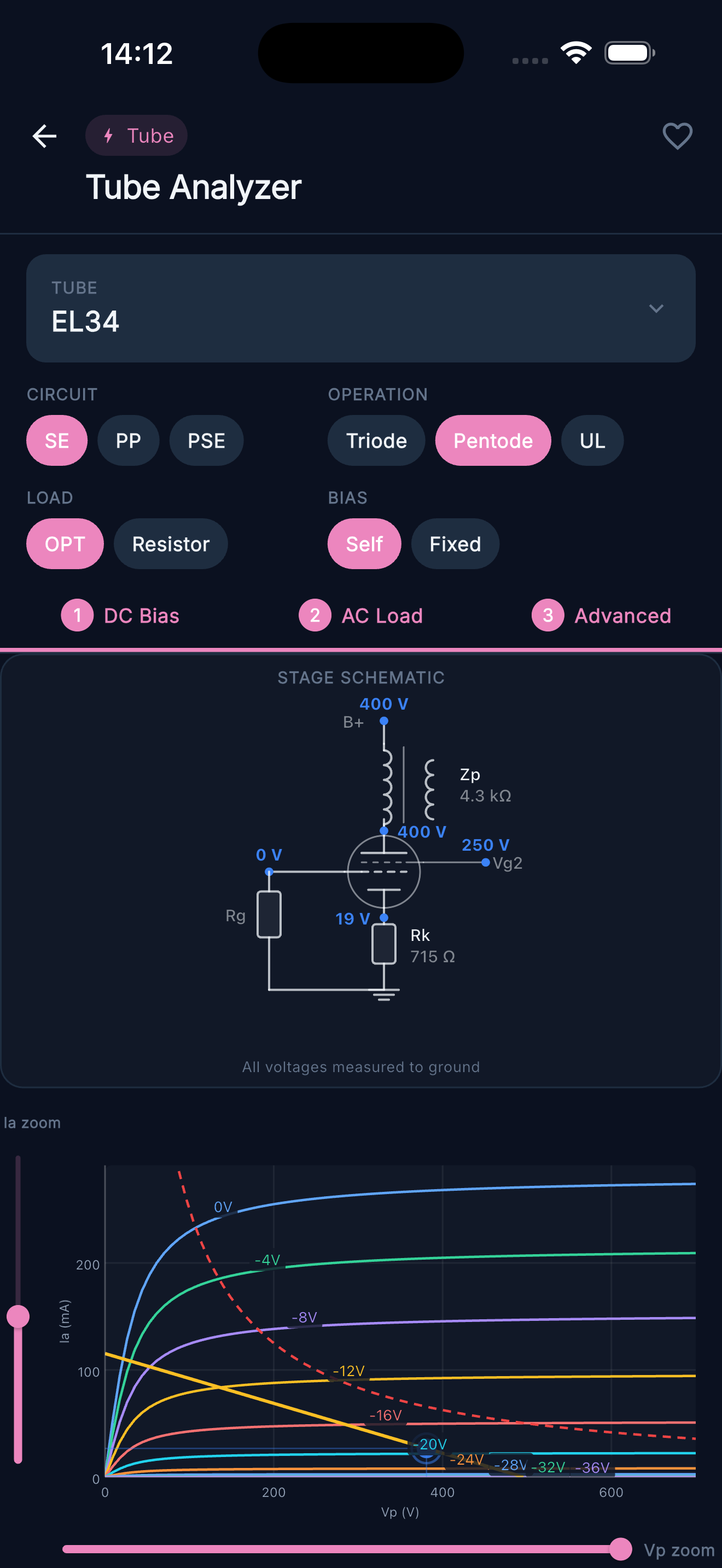
The app's flagship tool. Plot anode characteristic curves for triode, pentode, or ultralinear operation; draw the load line; set the Q-point; and read off voltage gain, output power, clipping margin and estimated 2nd harmonic -all from your own values.
How to use
What it's for
Design a complete valve stage on one screen — set an operating point, draw the load line, and read back gain, clean power and where the stage clips first.
You enter
- Tube — pick from the built-in database.
- Circuit — single-ended (SE), push-pull (PP) or PSE.
- Operation — triode, pentode or ultralinear (with UL tap %).
- Load — OPT or plate resistor, with load impedance Zp (or Zpp).
- Bias — self (cathode) or fixed.
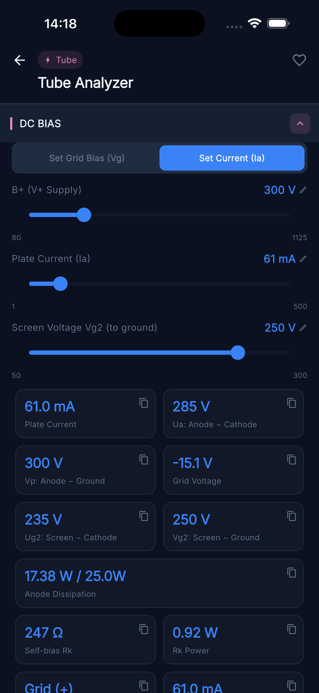
- Operating point — B+ supply, then Set Grid Bias (Vg) or Set Current (Ia).
- Signal — Vin peak (optional; drives the waveform and clipping display).
You get
- Anode characteristic curves with the load line, the Pa-max limit and the Q-point (independent Ia / Vp zoom).
- Operating point: plate current & voltage, grid voltage, screen voltage, anode dissipation.
- Bias: self-bias Rk and its dissipation.
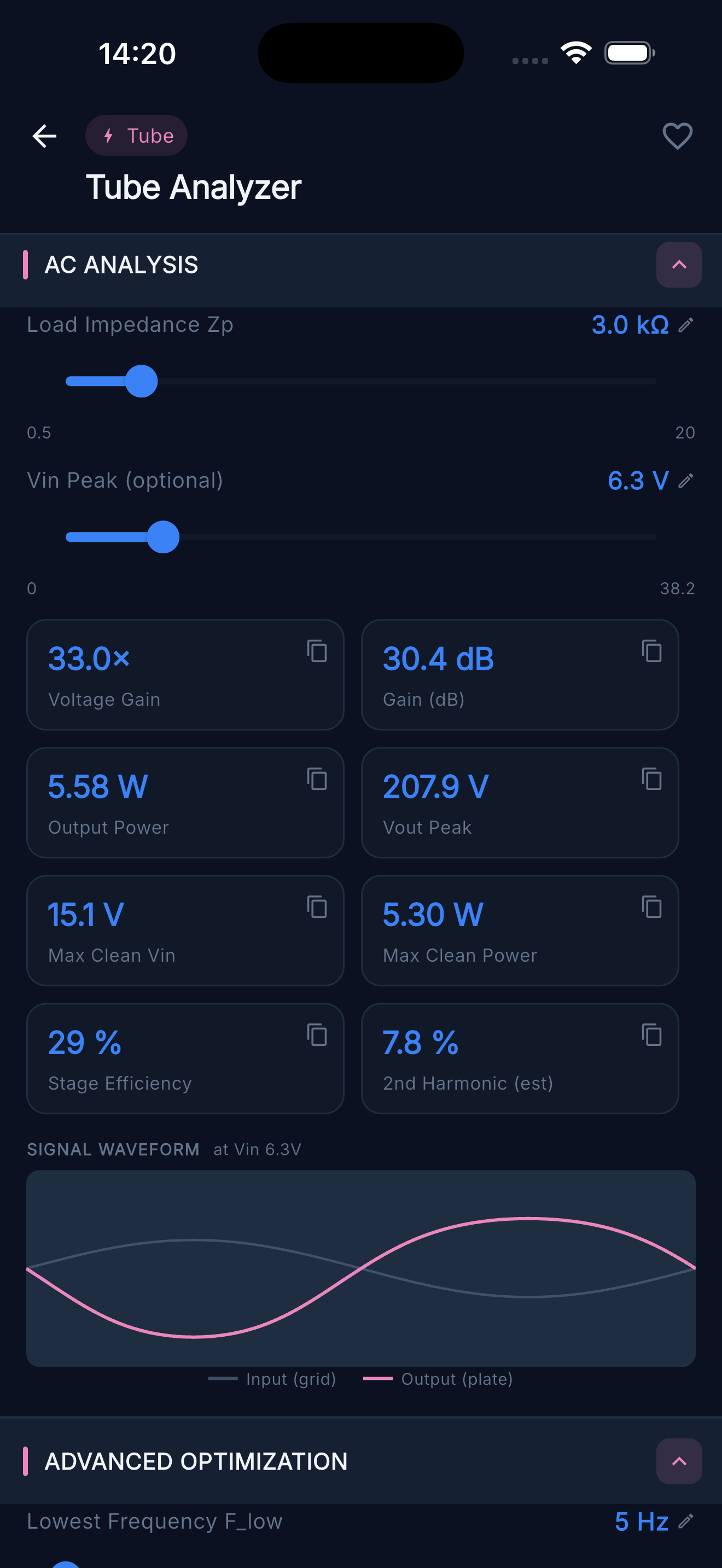
- AC performance: gain (× and dB), Vout peak, max clean Vin, max clean power, efficiency, estimated 2nd harmonic, and which side clips first.
- Input/output waveform with a clipping warning.
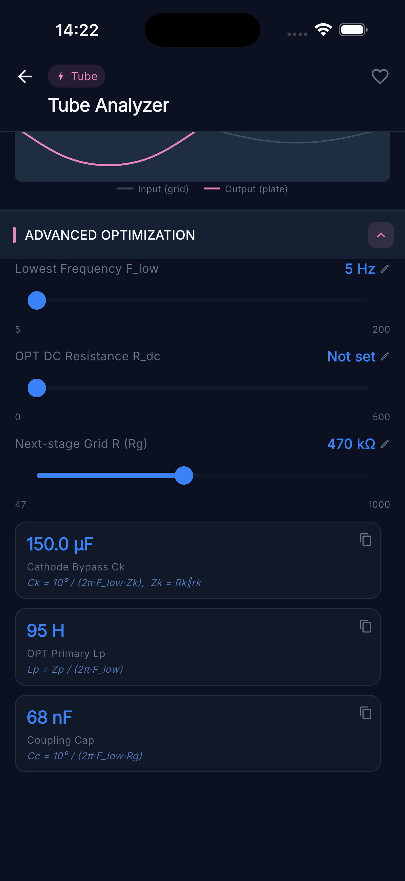
- Advanced: coupling cap, cathode bypass Ck, minimum OPT primary inductance, OPT DC resistance, B+ sag, next-stage grid resistor.
Tips & warnings
- Three working tabs: DC Bias → AC Load → Advanced.
- Warnings: dissipation exceeded (red), approaching the limit (amber), input driving the stage into clipping.
- Built on the original Koren model — the same maths SPICE uses.
Good to know
Cutoff & clipping: the operating point (Q) slides along the load line as signal is applied. One end is cutoff — the tube switches fully off, Ia = 0 and plate voltage peaks. The other end is the grid limit, where the grid nears 0 V and starts drawing current.
Because Q is rarely centred between those two ends, one is reached before the other as you turn the input up — the side with less headroom clips first. That shorter gap sets the max clean Vin and clean power.
If it clips first on the grid side, moving Q toward the centre (rebias, or change B+/load) balances the swing and buys more clean output. Cutoff-side and grid-side clipping also sound different (even vs odd harmonics), so where it clips first is partly a tonal choice.
Cutoff, clipping & the load line
With signal applied, the operating point (Q) slides along the load line between two limits. The side with less headroom clips first -and that sets your maximum clean output.
- Q · operating point
- Grid limit · clips first
- Cutoff · tube off, Ia = 0